Swift on Raspberry Pi Workshop: Part 3
Wrapping up our project
This is the third and final post in our three-part series about setting up a Raspberry Pi to build a distance measurement system for an autonomous car. In Part 1 of this series, we set up a basic circuit to control LEDs via the Raspberry Pi; and in Part 2, we started controlling those LEDs using Swift. If you‘re coming to this post first, I recommend checking out those posts first.
In this post, we‘re going to get started by adding a speaker to our circuit to make a sound.
Adding a speaker to our circuit
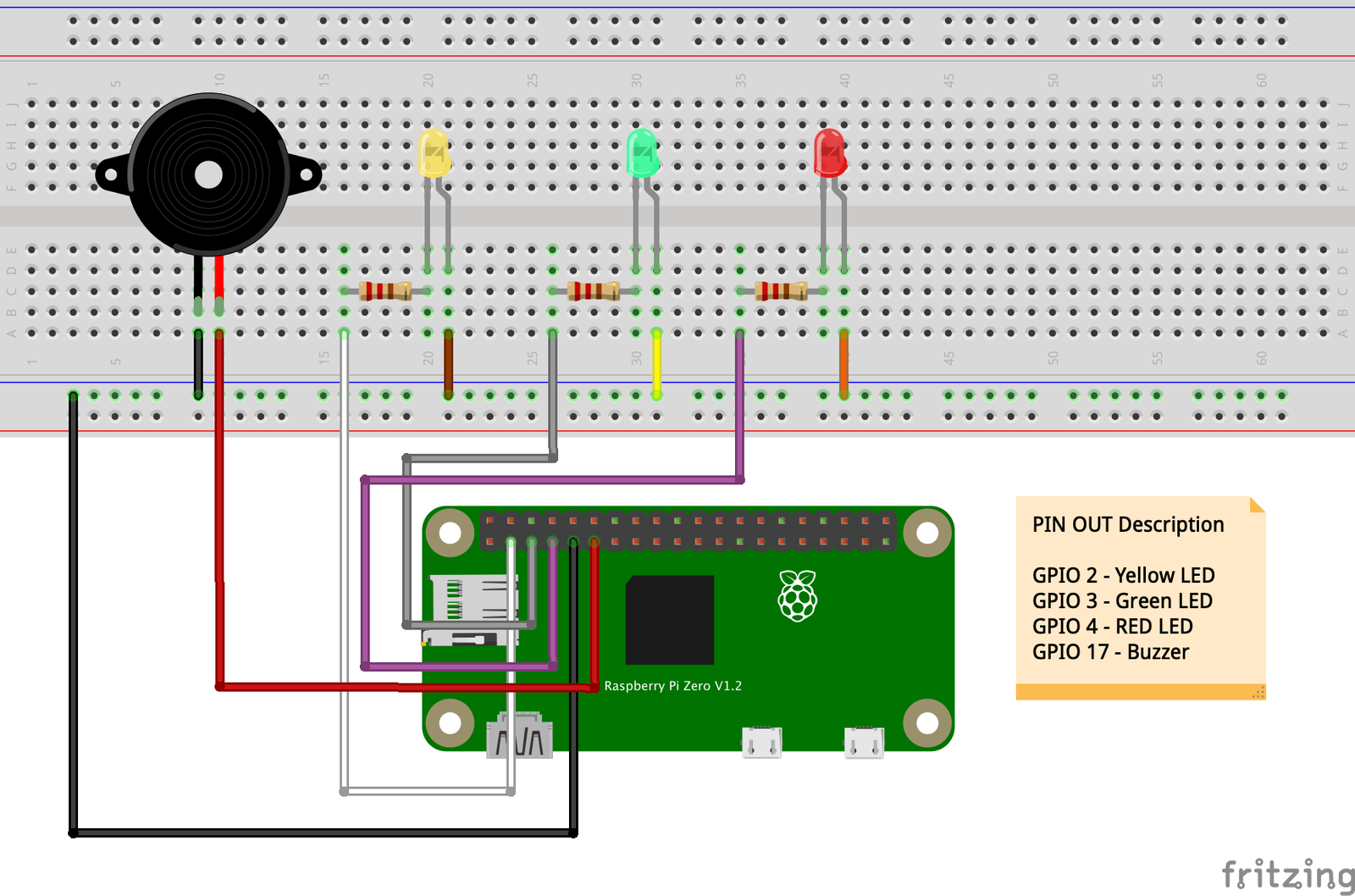
If you examine the picture below, you‘ll see an example circuit with the speaker connected. This circuit also has a few extra LEDs that we’ll use in our final circuit. For now, let‘s focus on connecting the speaker. For this, I’ll use ports 9A and 10A on the breadboard. You can use whichever ports you like. I‘m also going to use GPIO 17 (pin #11) on my Raspberry Pi to supply the voltage. For the ground connection, I’ll tap into my ground rail on the breadboard.
In Part 1, we used pin #9 from our Raspberry Pi to supply a ground connection to our breadboard. In order to use this ground, I‘ll use a jumper wire to go from the ground rail to port 9A. Then, I’ll connect a wire from GPIO 17 (pin #11) of my Raspberry Pi to port 10A of my breadboard. These connections are all we need to supply power to any port on row 10 A–E, as well as ground to any port on row 9 A–E. The final step is to place your speaker on any port in rows 9 and 10 A–E.
Controlling the speaker with Swift
Luckily for us, our speaker is a simple polarized component just like our LED. This means that it has a positive and negative side. In order to emit a sound, we just need to supply voltage to the positive side while grounding the negative side. The speaker will then make a sound as long as voltage is supplied. To make the sound stop, we just cut off the voltage or set it to low (0).
If you recall how we controlled our LED in the previous section, we will control our speaker in a similar fashion. Let‘s evaluate the code example below.
import SwiftyGPIO

// SwiftyGPIO configuration
// 1
let gpio = SwiftyGPIO.GPIOs(for: .RaspberryPi3)

//2
guard let led = gpio[.P2] else {
    fatalError("Could not initialize led.")
}

//3
guard let speaker = gpio[.P17] else {
    fatalError("Could not initialize speaker.")
}

//4
led.direction = .OUT

//5
speaker.direction = .OUT

//6
led.value = 1

//7
speaker.value = 1- Sets up our GPIO pins to be used.
- A reference to the LED controlled by GPIO 2.
- A reference to the speaker controlled by GPIO 17.
- Here we set the direction of the port. In this case, we are saying that the direction of GPIO 2 should be .OUT as in output. This means we want to output a signal/voltage from this pin.
- Sets the direction of GPIO 17 to be an .OUT as well.
- This sets the value of GPIO 2, which references our LED, to 1 or High. In layman‘s terms, this turns on the LED.
- This sets the value of GPIO 17, which references our speaker, to 1 or High. This emits a sound from the speaker.
If you build and execute this code on your Raspberry Pi, you should hear a sound coming from your speaker, and your LED should be lit.
Introducing the HC-SR04 Ultrasonic Sensor
Now that we know how to control a speaker and LED, we can leverage that knowledge to tie them into the final component of our system. This is by far the most complicated part—up to this point, we have been working with simple 2-pronged polarized components, but the HC-SRO4 has 4 prongs:
- VCC – This is our voltage pin. Here we supply the sensor with 5 volts. This is slightly more voltage than our LED and speaker require.
- Trig – This is our trigger pin. We use this pin to broadcast a sound wave.
- Echo – This is our echo pin. We use this pin to listen for the reply of the sound wave we broadcasted earlier.
- Gnd – This is our ground pin.
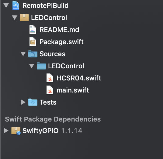
To measure distance, we are going to emit a sound, wait for a response, and measure the time it takes to get that response. This will allow us to know how far an object is from us. Writing the logic for this in Swift can be a bit tricky, so we are going to leverage the help of a package called HCSR04.swift.
If you have been following along with me, your project navigator should look like the image below:
With that code in place, we can now add some logic to our main.swift file and incorporate our HC-SR04 sensor. I‘ve also added a few extra LEDs to my circuit so that we can have our full monitoring system. See the code below:
import SwiftyGPIO
import Foundation

// SwiftyGPIO configuration
// 1
let gpio = SwiftyGPIO.GPIOs(for: .RaspberryPi3)

//2
guard let redLED = gpio[.P2] else {
    fatalError("Could not initialize red led.")
}

guard let yellowLED = gpio[.P3] else {
    fatalError("Could not initialize yellow led.")
}

guard let greenLED = gpio[.P4] else {
    fatalError("Could not initialize green led.")
}

guard let speaker = gpio[.P17] else {
    fatalError("Could not initialize speaker.")
}

//3
redLED.direction = .OUT
yellowLED.direction = .OUT
greenLED.direction = .OUT
speaker.direction = .OUT

//4
redLED.value = 0
yellowLED.value = 0
greenLED.value = 0
speaker.value = 0

//5
let sensor = HCSR04(usedRaspberry: .RaspberryPi3, echoConnectedPin: .P22, triggerConnectedPin: .P27, maximumSensorRange: 400)

//6
while true {
    do {
        let distance = try sensor.measureDistance()
        print("The distance is: \(distance)")
        switch distance {
        case 0..<5:
            print("Red zone")
            redLED.value = 1
            speaker.value = 1
            yellowLED.value = 0
            greenLED.value = 0
        case 5..<10:
            print("Yellow zone")
            redLED.value = 0
            speaker.value = 0
            yellowLED.value = 1
            greenLED.value = 0

        default:
            print("Green zone")
            redLED.value = 0
            speaker.value = 0
            yellowLED.value = 0
            greenLED.value = 1
        }
        Thread.sleep(forTimeInterval: 0.6)
    } catch {
        print("There was an error: \(error.localizedDescription)")
    }
}
Let‘s go through what the code is doing:
- In this step, we are initializing our GPIO pins.
- Here we are creating references to the various pins that correspond to our LEDs. These pin assignments directly reflect the cables that connect back to my Raspberry Pi as well as the connections on the breadboard.
- Here we set the direction of our ports. In this case, all of our LEDs are functioning as outputs because they are transforming voltage being supplied to them versus providing some sort of input voltage back to our Raspberry Pi.
- In this code block we ensure that every component starts in the off position. This ensures that our LEDs and speaker all start in the same state regardless of the state they were left in when the program last exited.
- This line sets up our HC-SRO4 sensor. This is possible because of the code that we copied in from the library. The pins specified are specifically based on the ports that my sensor is plugged into.
- Note: The maximum sensor range value is an arbitrary value that I chose based on the ranging distance listed on the box of the sensor. The maximum range is 500cm, but I decided to use 400cm to limit any chances of error.
- This is where all of the distance measurement happens. We first create an infinite while loop so that our sensor is continuously monitoring as long as the program is running. Our sensor has a method called
measureDistance()that returns aDoublein centimeters of the estimated distance. We then use aswitchstatement over that distance returned to determine what we want to do:- If the distance range is between 0cm and 4.9cm, we consider this our “Red zone”. If we are in this zone, we want to turn on the red LED as well as the speaker.
- If the distance range is between 5cm and 9.9cm, we consider this our “Yellow zone” and turn on the yellow LED.
- If the distance range is anything else, we consider this our green zone and turn on the green LED.
In order to ensure that the sensor has time to process the measurements, we sleep the thread or pause for 0.6 seconds in between each measurement. With all of that in place, you now have a fully function distance measurement system written in Swift!
Summary
In this series, we learned how to work with a breadboard, resistors, LEDs, HCSR04 sensor, buzzer and a Raspberry Pi to create a system that can measure differences. Our first step was to build a basic circuit that we could control with no Swift involvement, allowing us to verify that our connections are good and that we‘re not making a mistake in Xcode or in the transfer of our code. In Part 2, we introduced Xport and started writing Swift code to actually drive the logic on our board. Finally, we added a HCSR04 sensor to the equation so that we could measure distances and interact with the speaker and LEDs. Remember, most components require a (0) or a (1) to turn them off or on. With that knowledge, you can write some interesting logic that can interact with hardware based on the state of certain sensors.
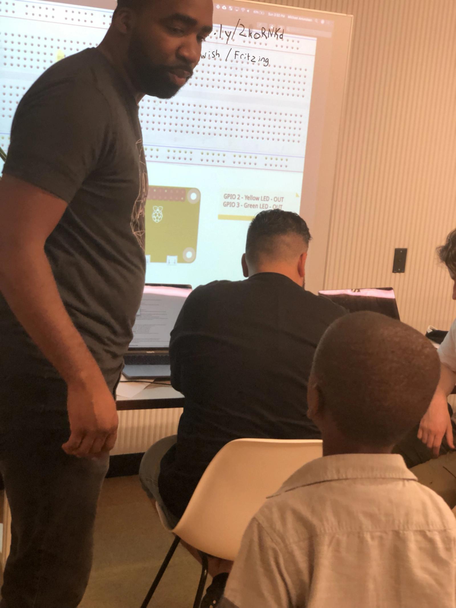
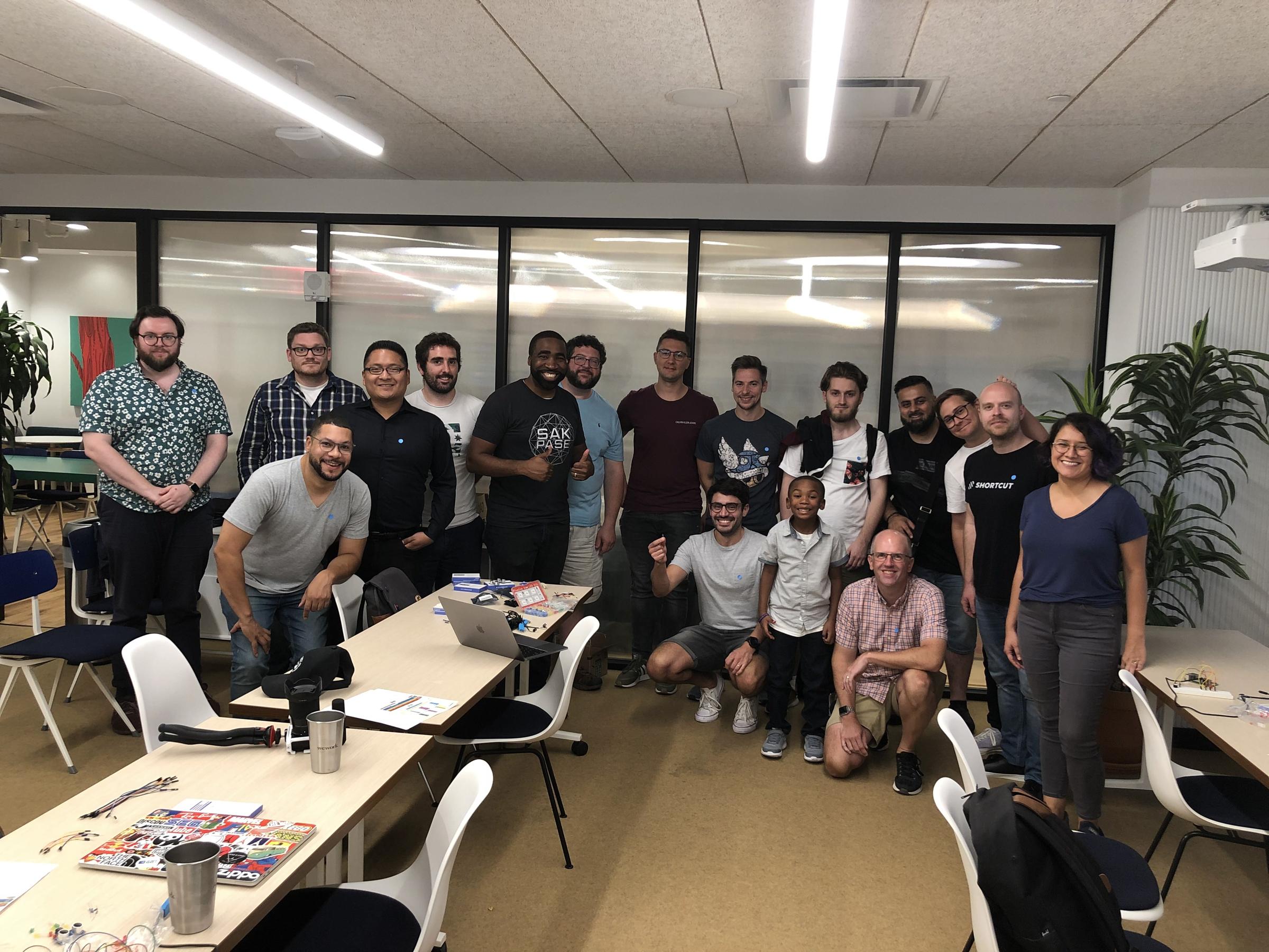
I had a tremendous amount of fun hosting this workshop, and met so many awesome developers from all over the world. However, the proudest moment for me was being able to have my firstborn son present to see Daddy in his element. The Raspberry Pi is an amazing device for all ages, and after the workshop, my son was anxious for us to build a project together. If your target group is children, you can also use programs like Scratch to control your circuits. I highly recommend visiting the projects page on the official Raspberry Pi website for ideas.