Swift on Raspberry Pi Workshop: Part 1
Setting up a basic circuit

The Raspberry Pi is a fun little device that everyone can learn from. From robotics to home automation, you can use it to do just about anything. In September 2019, I hosted a workshop at try! Swift NYC where we used a Raspberry Pi to build a distance measurement system for an autonomous car.
How does this distance measurement system work? Essentially, we will measure the distance between an object and an HC-SR04 sensor. If we are far enough away from the sensor, a green LED will light up; if we get closer, a yellow LED will light up; and if we get too close, a red LED will light up and a speaker will emit a warning sound.
This is the first post in a three-part series about that workshop—today, we’ll cover how to set up a basic circuit that controls LEDs via the Raspberry Pi. Let’s start building our system!
What you‘ll need
To put the full system together, you‘ll need the following parts:
- Breadboard – This will act as the circuit board for our system, connecting all of our components so they can interact with one another.
- Raspberry Pi – This will be the brain of our system. I used a Raspberry Pi 3 Model B+, but you can certainly use a Pi Zero or any other model.
- LED Kit – If you are hosting a workshop, you‘ll need multiple LEDs for each person to use. This kit is what I used in the workshop and it includes 100, 200-ohm resistors to protect the LEDs.
- Active Buzzer – This will be the speaker that alerts us when we get too close to the sensor.
- HC-SR04 Ultrasonic Sensor – This sensor uses sonic waves to measure the distance of an object.
- Resistors – For this experiment, we need both 200-ohm resistors for our LEDs and 1K ohm resistors for our ultrasonic sensor circuit.
- PL2303TA USB to TTL Serial Cable Debug Console Cable – This cable is optional, but useful for workshop-like environments where you don‘t have access to a monitor to connect the Raspberry Pi to. It allows you to establish a serial connection between your computer and the Raspberry Pi, which will allow you to communicate with the Pi without having a network connection or monitor.
For software, you‘ll need the following:
- Xcode – I am currently using Xcode 12. We will use Xcode to write our Swift code and send it to the Raspberry Pi.
- Swish – This is a simple script for remote building your Swift projects on a Linux machine, such as a Raspberry Pi. If we didn‘t use this script, we would need to develop completely on the Raspberry Pi or manually copy all of our files from our MacBook to the Raspberry Pi.
- Fritzing – This is an open-source hardware initiative that makes electronics accessible as a creative material for everyone. I used it to mock up the circuit designs to make the workshop easier to follow, as you‘ll see below.
Connecting to your Raspberry Pi
You‘ll need to install Swift on your Raspberry Pi, which I covered in a previous blog post. But first, you‘ll need to connect to your Raspberry Pi. You can do this by attaching a monitor, keyboard, and mouse—but it would be very difficult to set up 20 monitors for a workshop, so to work around this, you can connect to the Pi using the USB to TTL serial cable listed above:
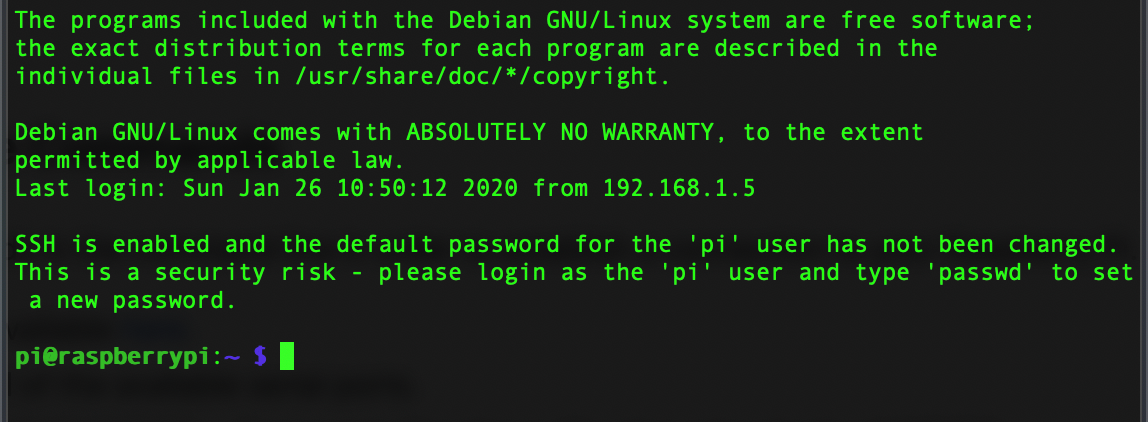
Step 2
- Install a driver
- Follow the tutorial found here and enter a few commands. I had mixed results, but this is by far the quickest way to connect to a Raspberry Pi without a monitor. Once you‘re connected, your terminal window should look like the image above.
- To get your Pi on the network, launch raspi-config and use the prompts to select network options and specify an SSID and password. (If you know the credentials for the WiFi network you‘re connecting to ahead of time, this method to connect to a “headless” Pi also works very well.)
- Enter the command
ping raspberrypi.localto get your Pi‘s IP address to connect to it. For more help, check out the official docs here. - Once you have your IP address, you‘re ready to create an SSH session to communicate remotely with your Pi. Type
ssh pi@<YOUR_IP_ADDRESS>into the terminal and selectYESat the next prompt to validate whether or not you trust the connection.
Once you‘re connected to your Raspberry Pi, you’re ready to rock and roll! Now, we can start to build our circuits on the breadboard.
Building the circuit
Parts of the circuit
To build our circuit, we’ll first need to have a basic understanding of the parts we’ll be using.
The breadboard is the glue that connects all of our components. Mine is broken up into three sections: the two outer sections are our power grids, with + and − representing the positive voltage and ground, respectively. The middle section, where our circuit will live, has columns labeled A–J and rows labeled 1–63. Between columns E and F, there is a bridge that splits the middle section in half.
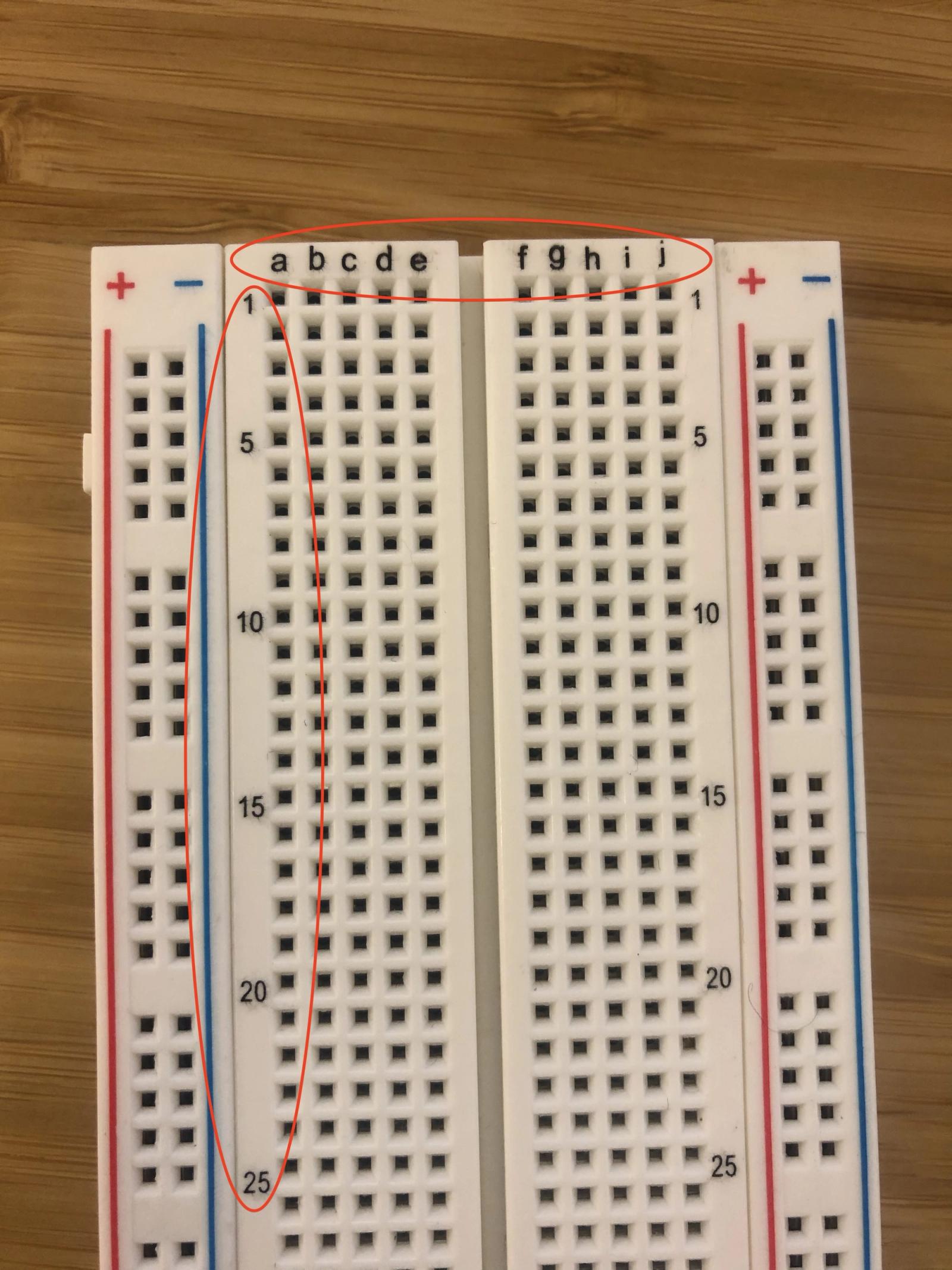
An example breadboard
We‘ll power our circuit through code with a General Purpose Input Output pin. GPIO pins can be set to low (0) or high (1)—a majority of pins provide a voltage of 3.3V when set to high.
Our LED is just a semiconductor that converts electricity into light. We provide the power, and it provides the light. This is a polarized component, which means we‘ll provide power to one side and ground to the other.
We could connect the LED directly to our power source, but it‘s best practice to protect it from being “burned out” or overpowered by using a resistor, which limits how much current flows through the LED. In my workshop, I used the 220-ohm resistor that came with my LED kit.
How to build the circuit
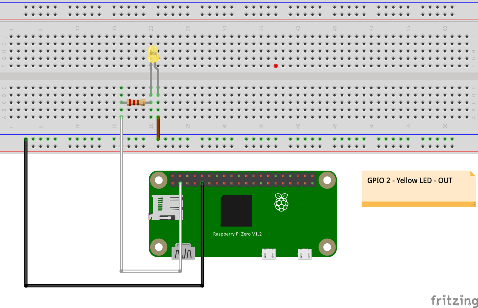
Building our circuit
First, provide a ground connection to the breadboard by plugging a jumper cable from GPIO pin #9 on the Raspberry Pi to the − column on the breadboard.
Instead of connecting to the + rail, connect a jumper cable from GPIO 2 (pin #3) to port 16A (row 16, column A) on the breadboard—this will provide power to every port in row 16, shown by the green dots in the example image above.
Next, insert a resistor into the circuit to limit the flow of current across our LED. Installing our resistor horizontally on row 16 before our bridge will cancel it out—so I’ve installed it vertically, from port 16C to 20C, to continue our connection down to row 20.
Now, connect the anode (the long, positive side of the LED) to port 20D and the cathode (the short, negative side of the LED) to port 21D.
Remember: Earlier, we provided a ground connection from our Pi to the ground rail of the breadboard via a jumper cable. This connection completes our circuit—our LED is now grounded by pin #9 and powered by GPIO 2 (pin #3).
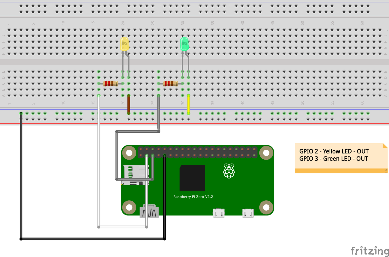
To add a second LED: connect a jumper cable from GPIO 3 (pin #5) to port 25S on the breadboard, connect a resistor from 25C to 30C, and connect the LED to the breadboard just like we did before—with the anode connected to the row that the resistor is terminated at, and the cathode connected to the ground rail of the breadboard.
Testing your circuit from the command line
By default, the WiringPi library is installed with the Raspbian OS image. This library provides a very easy means of testing your circuit without any configuration or third party software. If, for example, you wanted to test the LED connected to GPIO 2 (pin #3), you could enter the following commands:
gpio -g mode 2 output – Sets GPIO 2 pin as an OUTPUT pin.
gpio -g write 2 0 – Sets the GPIO 2 pin LOW or OFF.
gpio -g write 2 1 – Sets the GPIO 2 pin HIGH or ON.
We specify the port after the mode keyword or after the write keyword. With that knowledge, you can use the library to test any port you like.
What‘s next
In Part 2 of this series, we‘ll create the external build system we need to build and transfer our code from our computer to our Raspberry Pi, and get started writing some Swift code to control our LED.